
Project · Fuzz Tones
Shin Ei™ Companion™ Fuzz™
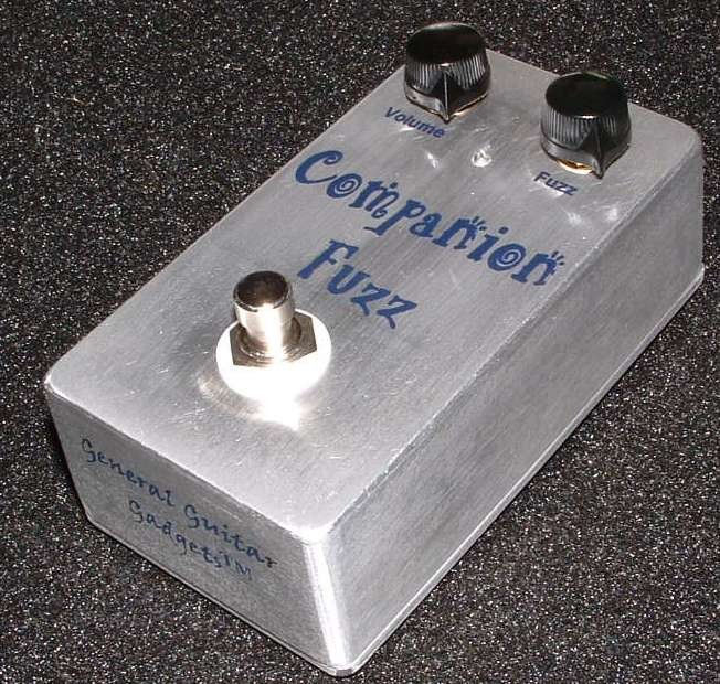
Heavy Duty Raw Fuzz Tone. This project now includes a transparent booster stage on the output to greatly increase the volume output without altering the sound of the fuzz. This is the Shin Ei™ FY-2, this is not the Shin Ei™ FY-6 which is the re-branded Super Fuzz™. Again, this is not the Super Fuzz™, but it is an awesome, raw, heavy fuzztone.
The story
About the circuit
The Shin-ei™ FY-2 Companion™ Fuzz was built in Japan in the late 1960s and sold under a dozen brand names around the world. It is a two-transistor fuzz with one job: to sound as raw and ragged as possible. It has very little output, a gated, sputtering decay and almost no bottom end, and that is exactly why it has a cult following; Dan Auerbach of the Black Keys made it famous again in the 2000s. It is not the FY-6, the six-transistor circuit that became the Univox™ Super-Fuzz, and the two sound nothing alike.
This project at GGG
Our SECF board was designed to build several of the simple '60s fuzzes, and the Companion™ Fuzz is the one it is named for. The original's biggest practical problem is its low output, so we added a transparent booster stage after the fuzz that brings the level up without changing the sound. The kit ships with everything for a 125B enclosure, and the page says it plainly: this is not the Super-Fuzz, but it is an awesome, raw, heavy fuzz tone.
Project files
Everything you need to build it
Shin Ei™ Companion™ Fuzz™ Ready-For-Transfer Printed Circuit Board Layout - For use only if you are a complete DIY person who wants to etch and drill your own PCB. Otherwise, we recommend you ignore this PCB mask and buy the Ready-to-Solder Printed Circuit Board or Complete Kit.
Schematic
Schematic
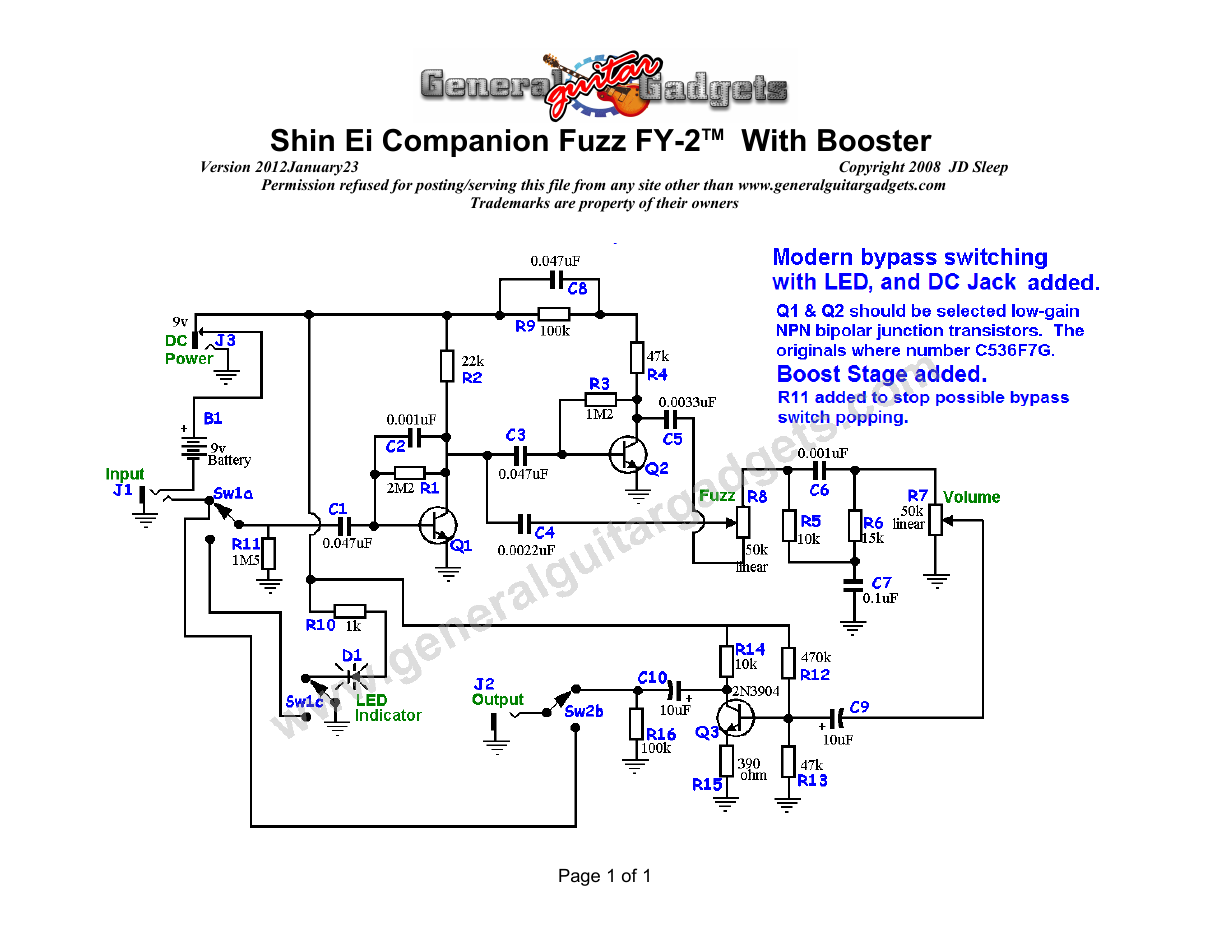
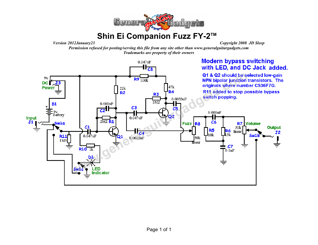
Parts layout
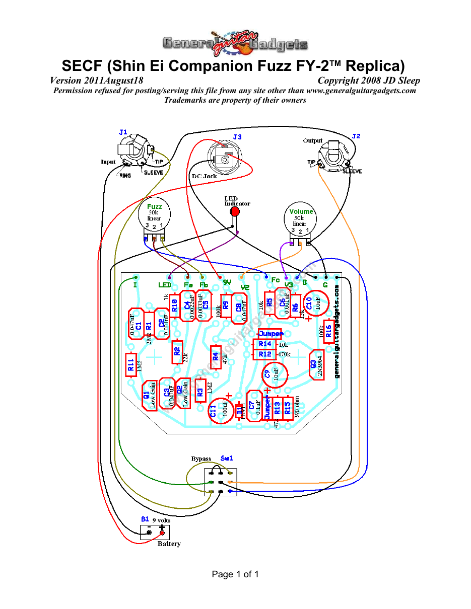
Parts Layout / Wiring Diagram
What you will need
Bill of Materials
Version 2009May26 · Copyright 2006 JD Sleep · Permission refused for posting/serving this file from any site other than www.generalguitargadgets.com · Trademarks are property of their owners
Resistors
| Resistor ID | Value | 3-band Marking | 4-band Marking |
|---|---|---|---|
| R1 | 2M2 (2.2 M) | red-red-green | red-red-black-yellow |
| R2 | 22k | red-red-orange | red-red-black-red |
| R3 | 1M2 (1.2 M) | brown-red-green | brown-red-black-yellow |
| R4 | 47k | yellow-violet-orange | yellow-violet-black-red |
| R5 | 10k | brown-black-orange | brown-black-black-red |
| R6 | 15k | brown-green-orange | brown-green-black-red |
| R9 | 100k | brown-black-yellow | brown-black-black-orange |
| R10 | 1k | brown-black-red | brown-black-black-brown |
| R11(Optional) | 1M5 | brown-green-green | brown-green-black-yellow |
| R12 | 470k | yellow-violet-yellow | yellow-violet-black-orange |
| R13 | 47k | yellow-violet-orange | yellow-violet-black-red |
| R14 | 10k | brown-black-orange | brown-black-black-red |
| R15 | 390 ohm | orange-white-brown | orange-white-black-black |
| R16 | 100k | brown-black-yellow | brown-black-black-orange |
Capacitors
| Capacitor ID | Value | Type | Possible Marking |
|---|---|---|---|
| C1 | 0.047µF | Film | 473 |
| C2 | 0.001µF | Film | 102 |
| C3 | 0.047µF | Film | 473 |
| C4 | 0.0022µF | Film | 222 |
| C5 | 0.0033µF | Film | 332 |
| C6 | 0.001µF | Film | 102 |
| C7 | 0.1µF | Film | 104 |
| C8 | 0.047µF | Film | 473 |
| C9 | 10µF | Aluminum Electrolytic | 10µF |
| C10 | 10µF | Aluminum Electrolytic | 10µF |
| C11 | 100µF | Aluminum Electrolytic | 100µF |
Potentiometers
| Part ID | Value | Type |
|---|---|---|
| R7 - Volume Control | 50k | Linear Taper |
| R8 - Fuzz Control | 50k | Linear Taper |
Other
| Part ID | Part Name |
|---|---|
| Q1 | low-gain NPN bipolar junction transistor |
| Q2 | low-gain NPN bipolar junction transistor |
| Q3 | 2N3904 |
| D1 | 1N4001 or other |
| J1 | Stereo quarter-inch jack |
| J2 | Mono quarter-inch jack |
| J3 | DC Jack |
| B1 | 9 volt battery (not included in the Kit) |
| Sw1 | Heavy Duty 3PDT foot switch 9v battery snap, Printed Circuit Board, 24 gauge stranded wire, Enclosure, Knobs |
Examples of low-gain NPN bipolar junction transistors: ● 2N3904 ● 2N4401 ● BC546A ● BC547A ● BC548A ● BC549A
How to build it
Instructions
Version 2012February02 · Copyright 2006 JD Sleep · Permission refused for posting/serving this file from any site other than www.generalguitargadgets.com · Trademarks are property of their owners
This is a replica of the Shin EiTM Companion™ Fuzz FY-2TM referred to as SECF in these documents. This fuzz is rough and nasty, but doesn't seem to sputter at the trail end of longer notes the way some of these 1960's type fuzz units seem to do. The problem of low volume has been addressed in this project by the addition of a boost stage at the tail end of the circuit. We tried the other gain adding mods, as detailed in the SECF Modifications document, but found that they change the overall sound of the unit. The boost keeps all the characteristics of this fuzz intact and gives you plenty of volume. Thanks to Gasper Vozelj for designing and implementing the boost stage. This fuzz has a mid range (scoop) filter stage that really sets it apart from the similar MosriteTM FuzzriteTM. This gives the overall sound of the fuzz added fullness, a good deep bass tone and clear highs, which is unique for a simple Fuzz. We don't know of a source for the original C536F7G transistors. We tried several types of transistors and our findings were that The higher the Hfe of the transistors used, the nastier the fuzz. e.g. the low gain transistors such as 2N2222 seemed give a smoother fuzz than say, high gain 2N5089 transistors. Follow the PDF diagram for parts placement. Please Note: The two 10uF capacitors in the Booster section are labeled incorrectly on the PCB. Follow the parts placement diagram for capacitors C8, C9 and C10. R17 is not used and should be left empty. The two jumpers are not needed if you are using the GGG PCB (they're already built into the top layer of the PCB).
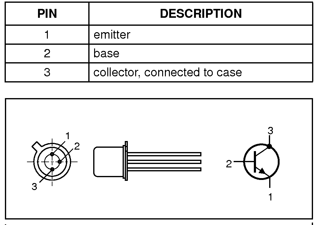
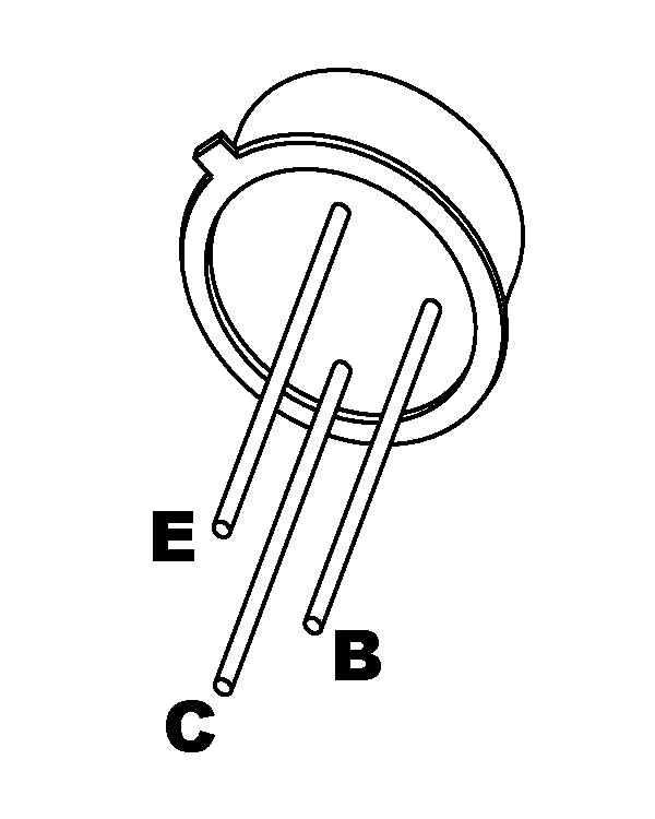
The Kits may have “can” (TO18) transistors for Q1 and Q2. If so, use the diagrams below to determine the pin orientation of the transistors:
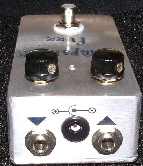
Here's an inside view of the unit we built to how it looks when assembled in a 125B enclosure.
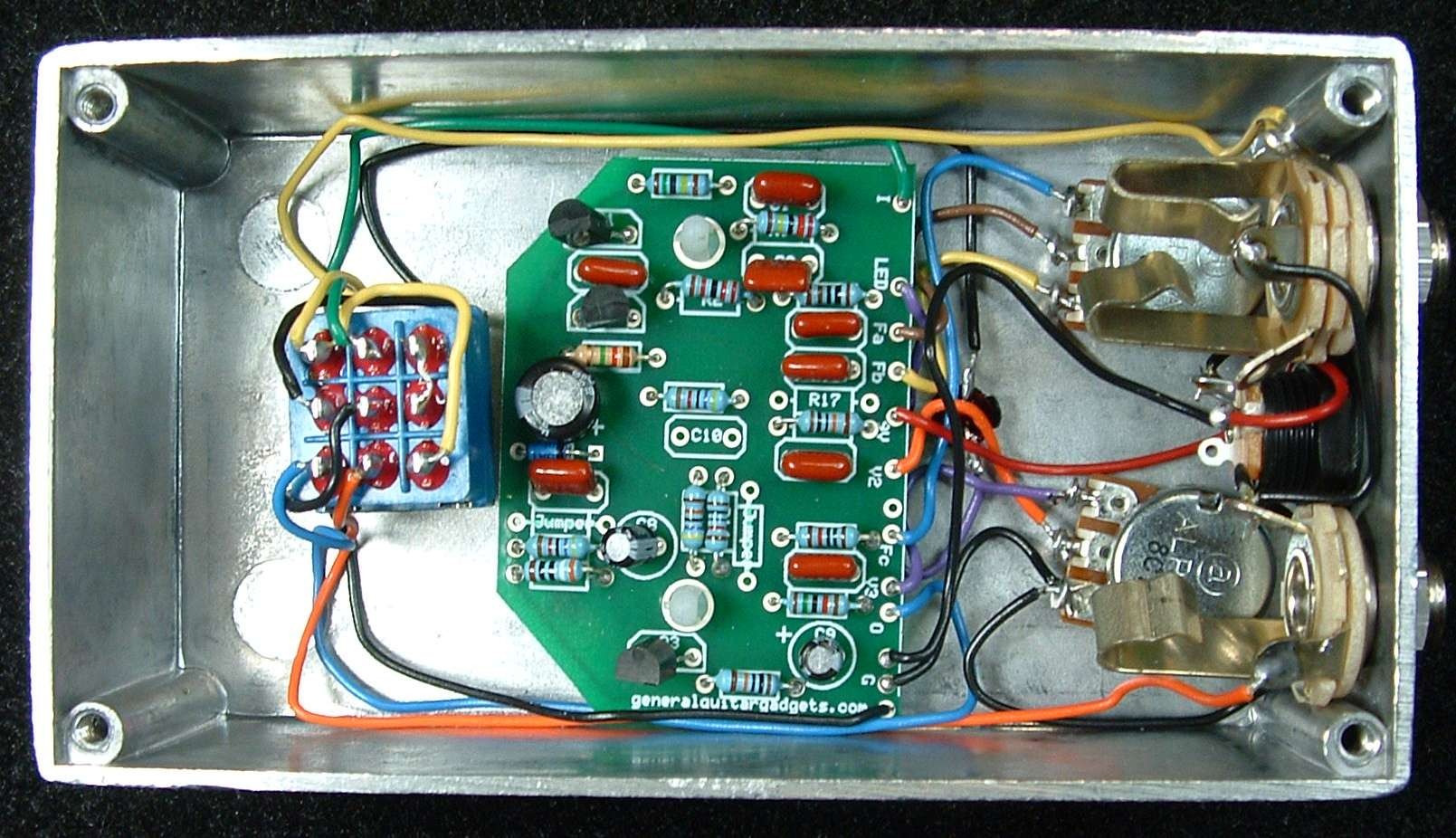
This is a fun effect, works well with other effects. Have fun, comments and questions are welcome and can be sent to [email protected] Here is a chart of voltages taken at the transistor pins. This information can be used to help you find and fix problems if your SECF doesn't work when you test it.
Component
Location
9 volt power supply Q1
Q2
Q3
Voltage
8.8v
Collector
6.6v
Base
0.6v
Emitter
0v
Collector
2.0v
Base
0.6v
Emitter
0v
Collector
6.6v
Base
0.7v
Emitter
0.1v
More about this project
Notes, sounds and related links

Ready to build? We have the kit.
Buy a SECF Complete Kit. Includes all the parts and materials you need to build one, all for about the price you would pay for a PCB and parts.
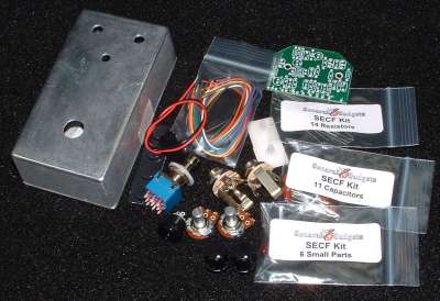
Would you like a Ready to Solder Circuit Board for this project? Note: If you buy the kit, the Ready-to-Solder Printed Circuit Board (RTS PCB) is included in the kit. You do not need to purchase this Ready to Solder Circuit Printed Board if you buy the kit.