
Project · Phase Shifters
MXR™ Phase 100™
This is the original MXR™ Phase 100™ Phase Shifter Replica known as P100. Thanks to Stephen Giles for sending some documents to make this project possible. Due to obsolete optical parts, we no longer stock the PCB or kit for this project, but the information is still available below. Any Trademarks mentioned here belong to their owners and not General Guitar Gadgets
Project files
Everything you need to build it
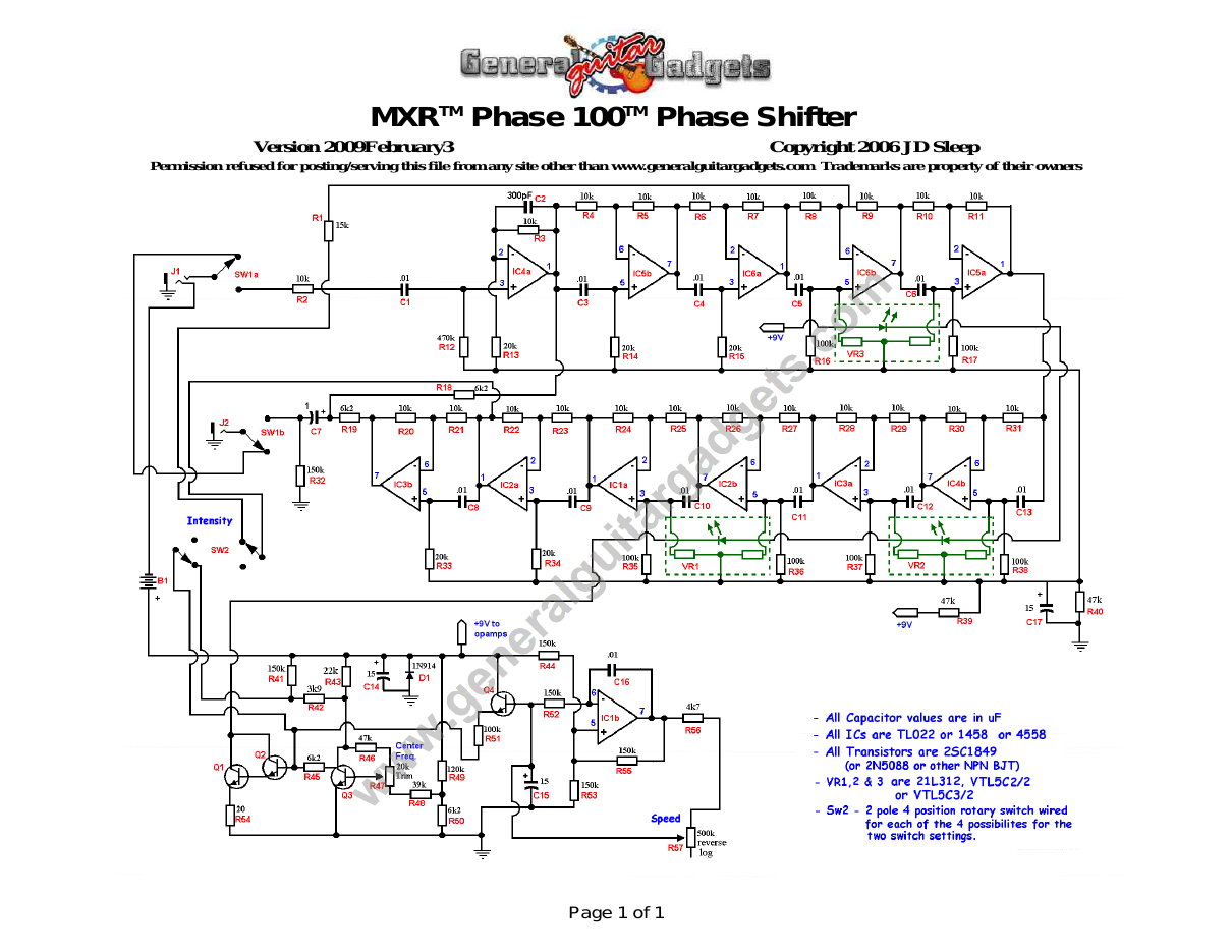
Parts layout
Parts Layout / Wiring Diagram
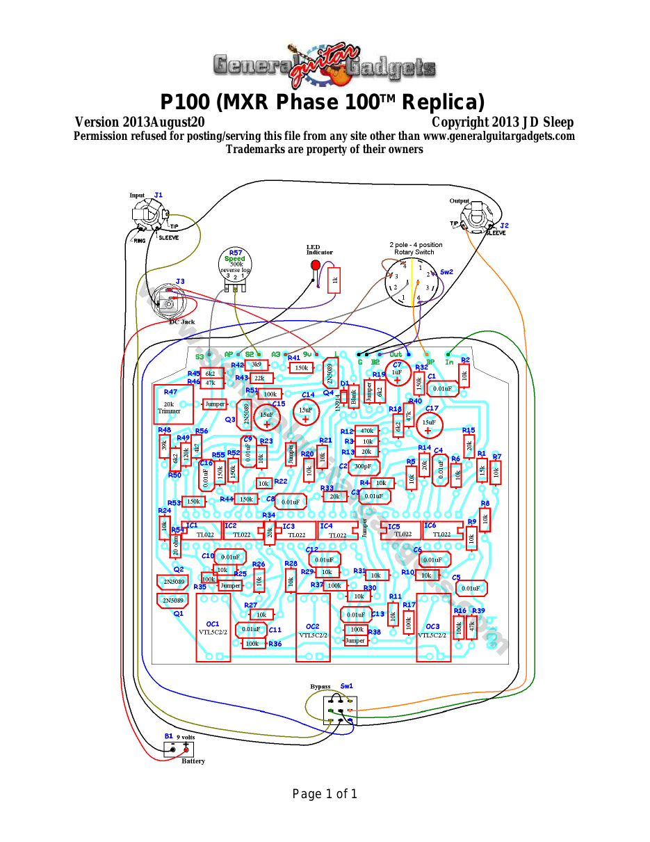
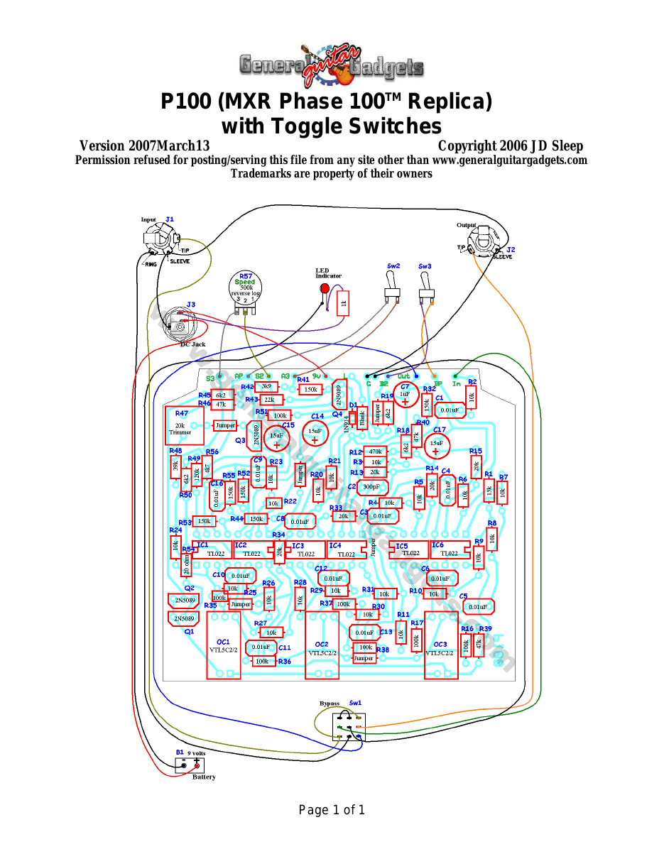
What you will need
Bill of Materials
Version 2009May26 · Copyright 2006 JD Sleep · Permission refused for posting/serving this file from any site other than www.generalguitargadgets.com · Trademarks are property of their owners
Resistors
| Resistor ID | Value | 3-band Marking | 4-band Marking |
|---|---|---|---|
| R1 | 15k | brown-green-orange | brown-green-black-red |
| R1 (alternate) | 29.4 | red-white-yellow-gold | |
| R2 | 10k | brown-black-orange | brown-black-black-red |
| R3 | 10k | brown-black-orange | brown-black-black-red |
| R4 | 10k | brown-black-orange | brown-black-black-red |
| R5 | 10k | brown-black-orange | brown-black-black-red |
| R6 | 10k | brown-black-orange | brown-black-black-red |
| R7 | 10k | brown-black-orange | brown-black-black-red |
| R8 | 10k | brown-black-orange | brown-black-black-red |
| R9 | 10k | brown-black-orange | brown-black-black-red |
| R10 | 10k | brown-black-orange | brown-black-black-red |
| R11 | 10k | brown-black-orange | brown-black-black-red |
| R12 | 470k | yellow-violet-yellow | yellow-violet-black-orange |
| R13 | 20k | red-black-orange | red-black-black-red |
| R14 | 20k | red-black-orange | red-black-black-red |
| R15 | 20k | red-black-orange | red-black-black-red |
| R16 | 100k | brown-black-yellow | brown-black-black-orange |
| R17 | 100k | brown-black-yellow | brown-black-black-orange |
| R18 | 6k2 (6.2k) | blue-red-red | blue-red-black-brown |
| R19 | 6k2 (6.2k) | blue-red-red | blue-red-black-brown |
| R20 | 10k | brown-black-orange | brown-black-black-red |
| R21 | 10k | brown-black-orange | brown-black-black-red |
| R22 | 10k | brown-black-orange | brown-black-black-red |
| R23 | 10k | brown-black-orange | brown-black-black-red |
| R24 | 10k | brown-black-orange | brown-black-black-red |
| R25 | 10k | brown-black-orange | brown-black-black-red |
| R26 | 10k | brown-black-orange | brown-black-black-red |
| R27 | 10k | brown-black-orange | brown-black-black-red |
| R28 | 10k | brown-black-orange | brown-black-black-red |
| R29 | 10k | brown-black-orange | brown-black-black-red |
| R30 | 10k | brown-black-orange | brown-black-black-red |
| R31 | 10k | brown-black-orange | brown-black-black-red |
| R32 | 150k | brown-green-yellow | brown-green-black-orange |
| R33 | 20k | red-black-orange | red-black-black-red |
| R34 | 20k | red-black-orange | red-black-black-red |
| R35 | 100k | brown-black-yellow | brown-black-black-orange |
| R36 | 100k | brown-black-yellow | brown-black-black-orange |
| R37 | 100k | brown-black-yellow | brown-black-black-orange |
| R38 | 100k | brown-black-yellow | brown-black-black-orange |
| R39 | 47k | yellow-violet-orange | yellow-violet-black-red |
| R40 | 47k | yellow-violet-orange | yellow-violet-black-red |
| R41 | 150k | brown-green-yellow | brown-green-black-orange |
| R42 | 3K9 (3.9K) | orange-white-red | orange-white-black-brown |
| R43 | 22k | red-red-orange | red-red-black-red |
| R44 | 150k | brown-green-yellow | brown-green-black-orange |
| R45 | 6k2 (6.2k) | blue-red-red | blue-red-black-brown |
| R46 | 47k | yellow-violet-orange | yellow-violet-black-red |
| R47 | 20k trimmer | ||
| R48 | 39k | orange-white-orange | orange-white-black-red |
| R49 | 120k | brown-red-yellow | brown-red-black-orange |
| R50 | 6k2 (6.2k) | blue-red-red | blue-red-black-brown |
| R51 | 100k | brown-black-yellow | brown-black-black-orange |
| R52 | 150k | brown-green-yellow | brown-green-black-orange |
| R53 | 150k | brown-green-yellow | brown-green-black-orange |
| R54 | 20 ohm | red-black-black | red-black-black-gold |
| R55 | 150k | brown-green-yellow | brown-green-black-orange |
| R56 | 4k7 (4.7k) | yellow-violet-red | yellow-violet-black-brown |
| R57 | Speed Control Potentiometer |
Capacitors
| Capacitor ID | Value | Type | Possible Marking |
|---|---|---|---|
| C1 | 0.01µF | Film | 103 |
| C2 | 300pF | Ceramic or Film | 301 (or 300pF) |
| C3 | 0.01µF | Film | 103 |
| C4 | 0.01µF | Film | 103 |
| C5 | 0.01µF | Film | 103 |
| C6 | 0.01µF | Film | 103 |
| C7 | 1µF | Tantalum ( or Aluminum Electrolytic) | 1µF |
| C8 | 0.01µF | Film | 103 |
| C9 | 0.01µF | Film | 103 |
| C10 | 0.01µF | Film | 103 |
| C11 | 0.01µF | Film | 103 |
| C12 | 0.01µF | Film | 103 |
| C13 | 0.01µF | Film | 103 |
| C14 | 15µF | Tantalum (or Aluminum Electrolytic) | 15µF |
| C15 | 15µF | Tantalum (or Aluminum Electrolytic) | 15µF |
| C16 | 0.01µF | Film | 103 |
| C17 | 15µF | Tantalum (or Aluminum Electrolytic) | 15µF |
Potentiometers
| Part ID | Value | Type |
|---|---|---|
| R47 - Center Frequency (trim) | 20k | Trimmer |
| R57 - Speed Control | 500k | Reverse Log Taper (or 100k linear) |
Other
| Part ID | Part Name |
|---|---|
| IC1, IC2, IC3, IC4, IC5, IC6 | TL022 |
| VR1, VR2, VR3 | VTL5C2/2 or VTL5C3/2 |
| 6 - jumper wires or 0 ohm resistors | Jumper (6 times) |
| D1 | 1N914 |
| D2 | LED (status indicator optional) |
| Q1 | 2N5088 (or other NPN BJT) Transistor |
| Q2 | 2N5088 (or other NPN BJT) Transistor |
| Q3 | 2N5088 (or other NPN BJT) Transistor |
| Q4 | 2N5088 (or other NPN BJT) Transistor |
| J1 | Stereo quarter-inch jack |
| J2 | Mono quarter-inch jack |
| J3 | DC Jack |
| B1 | 9 volt battery (not included in the Kit) |
| Sw1 | Heavy Duty 3PDT foot switch |
| Sw2 | 2-pole 4-way rotary switch ( or 2 SPST toggle switches) 9v battery snap, Printed Circuit Board, 24 gauge stranded wire, Enclosure, Knobs |
How to build it
Instructions
Version 2014June27 · Copyright 2013 JD Sleep · Permission refused for posting/serving this file from any site other than www.generalguitargadgets.com · Trademarks are property of their owners
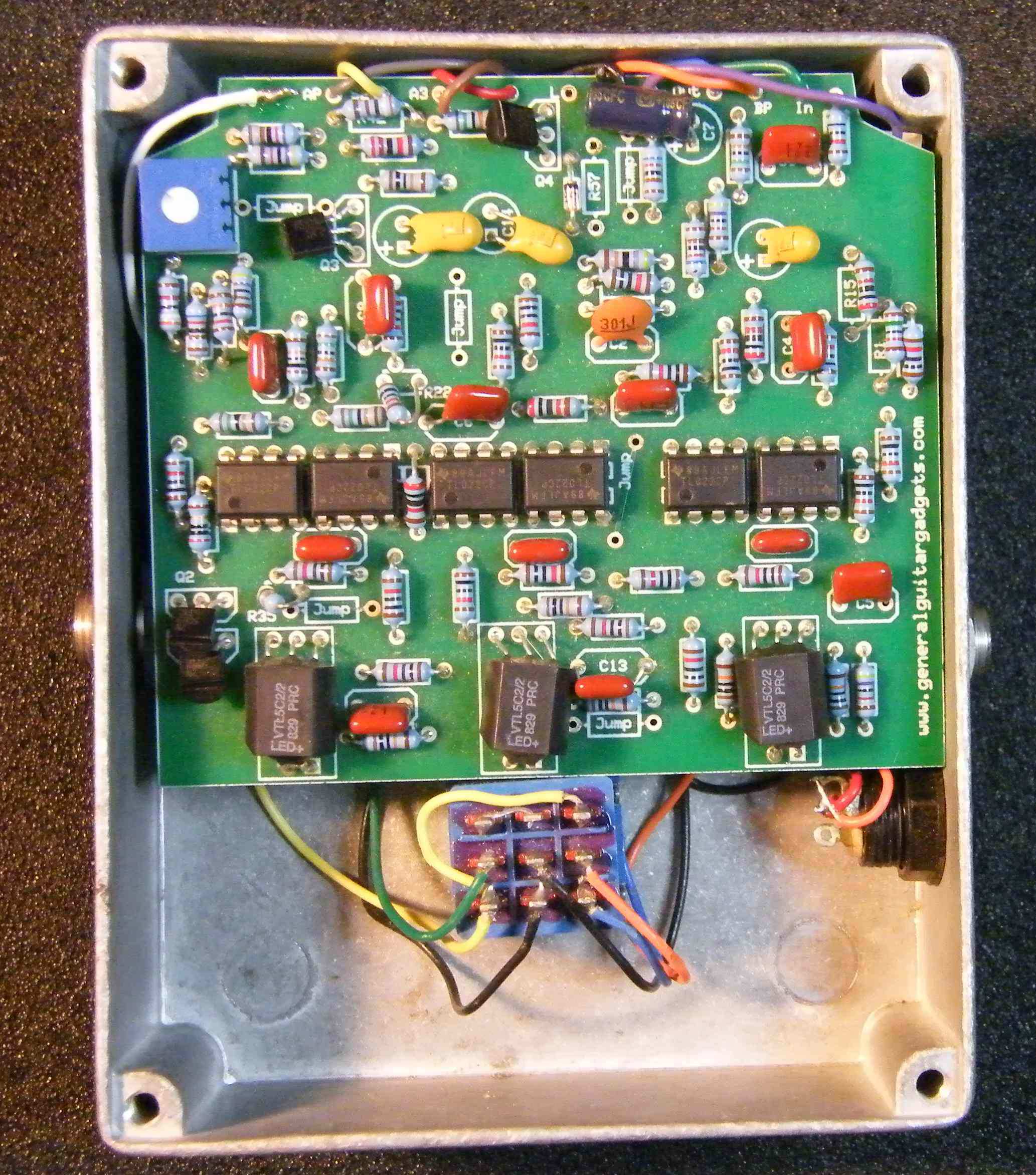
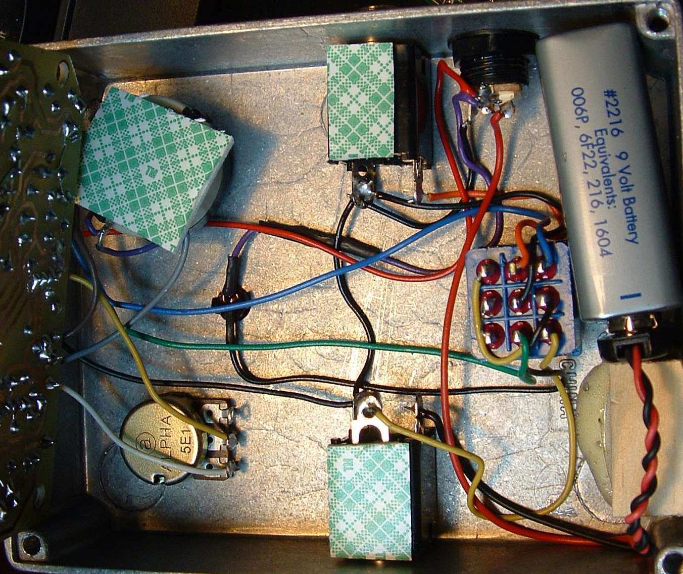
This is a replica of the MXRTM Phase 100TM referred to as P100 in these documents. This is a replica of the original, vintage, real MXRTM unit, not the DunlopTM reissue. This is very versatile and unique sounding 10 stage phase shifter. An excellent set of sounds controlled by a 4-way switch that ranges from mild phase sounds to an intense phase that almost borders on chorus pedal sounds. The unique sound of this unit can be heard, used by Keith Richards of the Rolling Stones on their song "Shattered" on the "Some Girls" CD Among many other recorded examples of that time period. Use the project documents provided, starting with the General Build Instructions. It will fit nicely in a 1590BB or 1590NS enclosure, with a little planning. We use a Lorlin (manufacturer name) PCB-mount 2-pole rotary switch that can be set to any number of positions up to 8. We chose the PCB-mount version to keep the profile low so the board would fit over it. We clipped off all the unused terminals and bent down the terminals that we soldered to. This kept the profile of the switch low enough to fit the board over it. Then we used double sided tape to hold the board in place and insulate the terminals of the rotary switch. The holes for the jacks need to be drilled as close to the top of the enclosure as possible and enclosed jacks should be used. All the “jumpers” are included in the top layer of the PCB, so you don't need to add any jumpers to the components of the PCB. When you install the capacitors, especially C7 if the radial capacitor is tall, make sure that you lay it down flat before you solder the leads. There's not much “head room” between the PCB and the bottom plate, so everything needs to be low as possible.
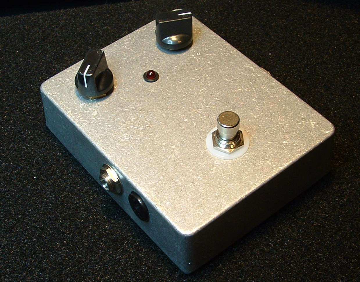
You can also see this in the photo below. The kit includes IC sockets. When we built this one, we decided not to socket anything. We're not against using sockets, but for whatever reason, we soldered the ICs straight to the PCB. In some cases the P100 will oscillate on the "regenerated" settings. This can be fixed by replacing the 15k R1 resistor with a higher value resistor. The kits include a 15k resistor and also a 29.4k resistor to use in R1 if you encounter oscillation. There are a couple of mistakes on the PCBs that need to be considered. The screen print on the top of the PCB shows the diode in the wrong direction. Follow the layout and look at the photo below for the correct installation of the diode. Also a last minute addition to the PCB to add the LED current limiting resistor (R59) is not correct, so you'll still need to add the 1k resistor inline with the LED wiring and don't add R59 to the PCB.
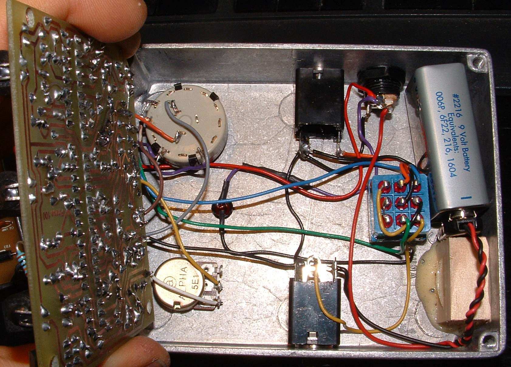
The kit comes with a Lorlin adjustable rotary switch. The collar around the pole should be set in position 4 when the switch has been turned to the most counter clockwise position. The back of the switch has numbers and the poles are labeled with letters. The chart below describes the connections to the switch using the wire colors shown in the wiring diagrams.
Pole A (Pad “AP”)
Pole C (Pad BP)
1
7
2
8 (Pad “B2”)
3 (Pad “A3”)
9
4 (Pad “A3”)
10 (Pad “B2”)
Comments and questions are welcome and can be sent to [email protected]