
Project · EQ
6-Band Graphic EQ
Thanks to Dean Hazelwanter for the layout. Great little Graphic EQ. Note that the most poputlar 6 string guitar version build is the 5-band with Gain control.
Project files
Everything you need to build it
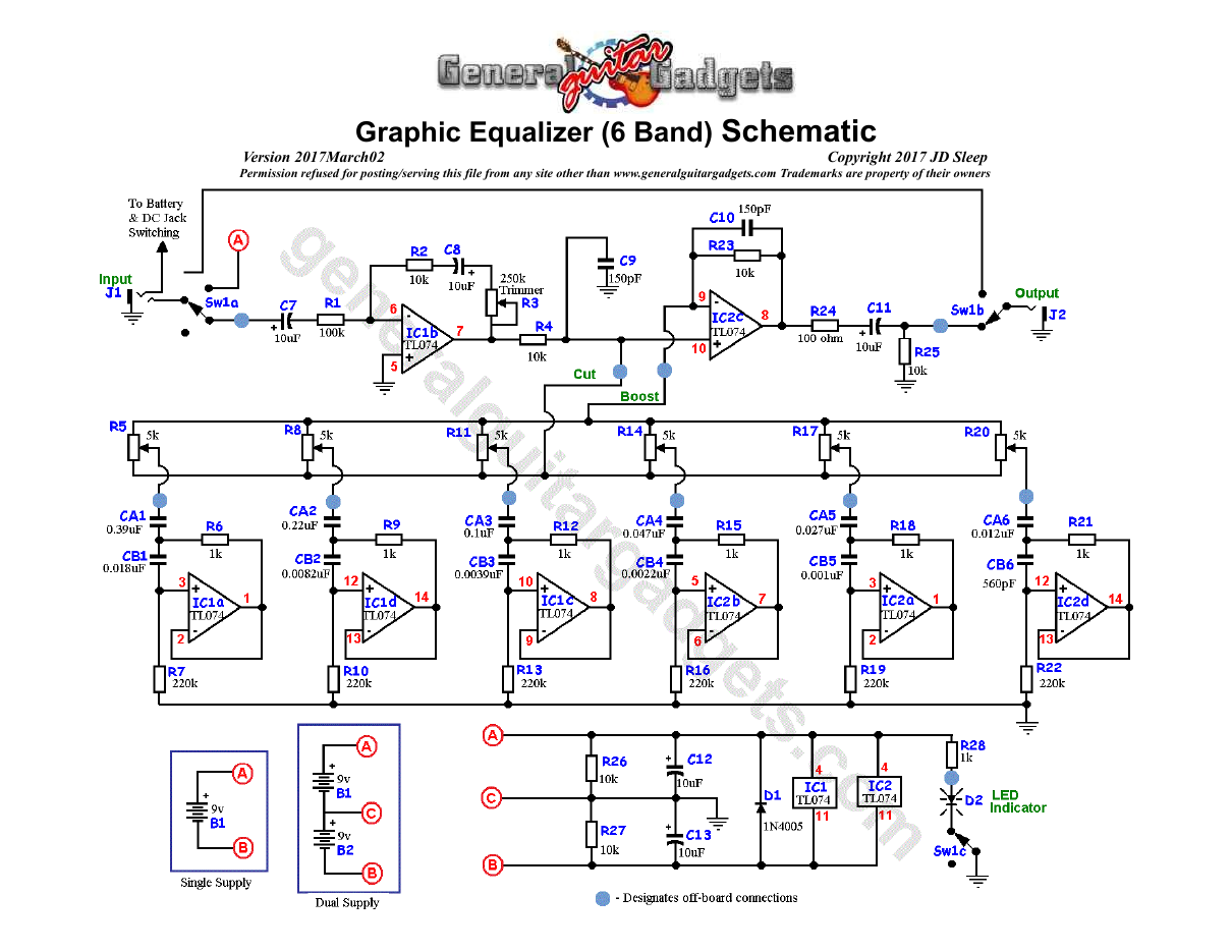
Parts layout
Parts Layout / Wiring Diagram
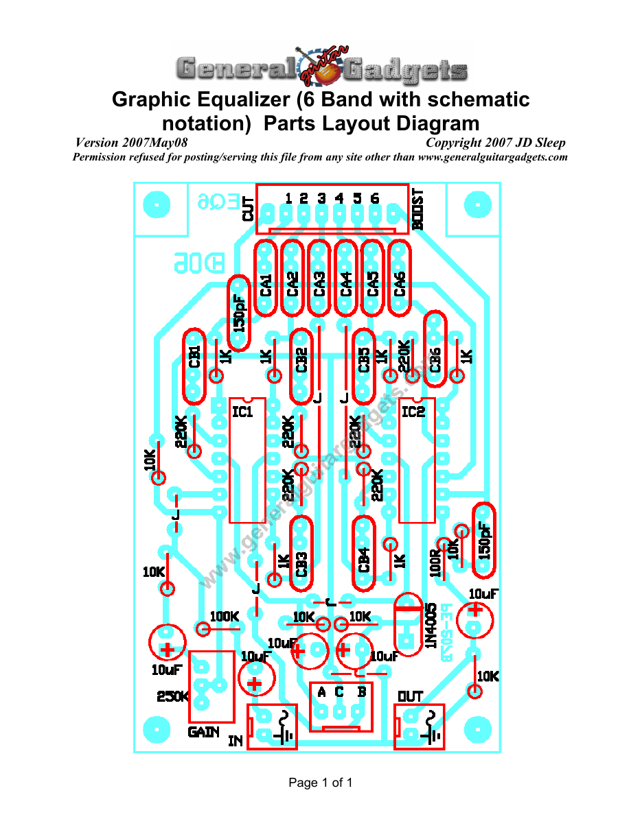
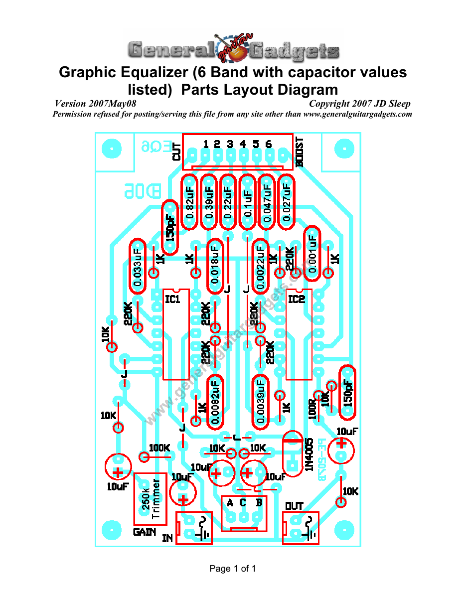
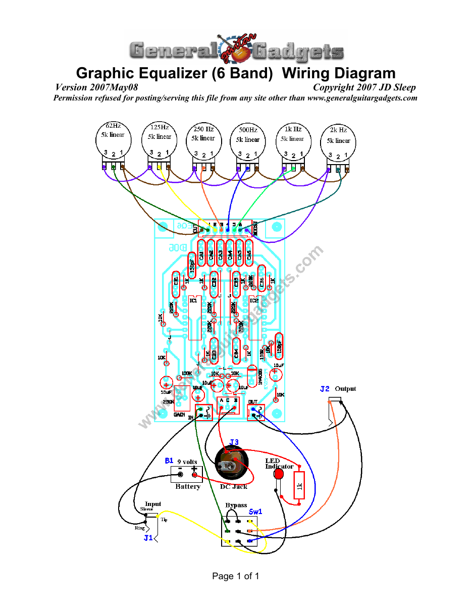
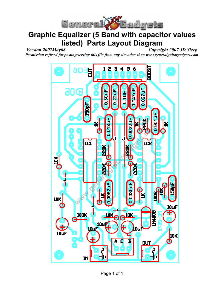
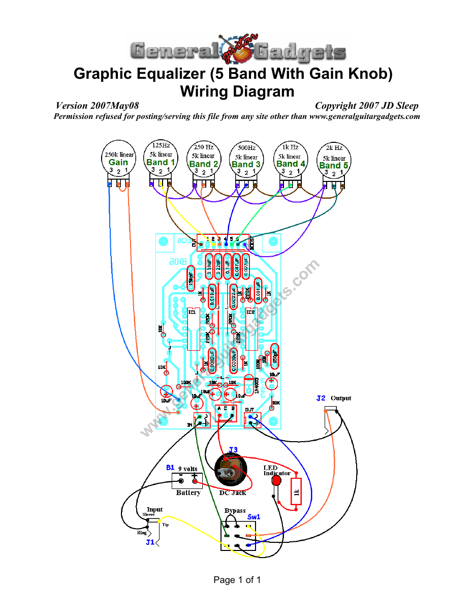
What you will need
Bill of Materials
Version 2009April20 · Copyright 2007 JD Sleep · Permission refused for posting/serving this file from any site other than www.generalguitargadgets.com · Trademarks are property of their owners
Resistors
| Resistor Count | Value | 3-band Marking | 4-band Marking |
|---|---|---|---|
| 6 | 0 ohm or jumper wire | black | black |
| 1 | 100 ohm | brown-black-brown | brown-black-black-black |
| 5 or 6 | 1k | brown-black-red | brown-black-black-brown |
| 6 | 10k | brown-black-orange | brown-black-black-red |
| 1 | 100k | brown-black-yellow | brown-black-black-orange |
| 5 or 6 | 220k | red-red-yellow | red-red-black-orange |
Potentiometers
| Part Count | Value | Type |
|---|---|---|
| 5 or 6 (for band controls) | 5k | Linear Taper |
| 1 (trimmer or potentiometer for Gain control) | 250k | Linear Taper |
Capacitors
| Capacitor Count or | Value | Type | Possible Marking |
|---|---|---|---|
| ID | |||
| 2 | 150pF | Ceramic or Film | 150pf or 151 |
| 5 | 10µF | Aluminum Electrolytic | 10uF |
| CA1 (for 6-band version only) | 0.82µF | Film | 824 |
| CB1 (for 6-band version only) | 0.039µF | Film | 393 |
| CA2 | 0.39µF | Film | 394 |
| CB2 | 0.018µF | Film | 183 |
| CA3 | 0.22µF | Film | 224 |
| CB3 | 0.0082µF | Film | 822 |
| CA4 | 0.1µF | Film | 104 |
| CB4 | 0.0039µF | Film | 392 or 3900pF |
| CA5 | 0.047µF | Film | 473 |
| CB5 | 0.0022µF | Film | 222 or 2200pF |
| CA6 | 0.027µF | Film | 273 |
| CB6 | 0.001µF | Film | 102 or 1000pF |
Other
| Part ID | Part Name |
|---|---|
| IC1 & IC2 | TL074 or other Quad opamp with the same pinout |
| Diode | 1N4005 |
| J1 | Stereo quarter-inch jack |
| J2 | Mono quarter-inch jack |
| J3 | DC Jack |
| B1 | 9 volt battery |
| Sw1 | Heavy Duty 3PDT footswitch 9v battery snap, PCB, 24 gauge stranded wire, Enclosure, knobs |
How to build it
Instructions
Version 2007May07 · Copyright 2007 JD Sleep · Permission refused for posting/serving this file from any site other than www.generalguitargadgets.com · Trademarks are property of their owners
Use the General Build Instructions document where applicable. Read and use the itemized notes that follow in this document. 1. This project is based on a 10 band October 1977 project from ETI (Electronics Today International). 2. The Gain control can be a trimmer or a panel mount potentiometer for ease of setting the gain and better use as a tone-controlled booster. 3. The center frequency of each band is determined by 2 caps, CA and CB. The schematic shows a table with values of CA and CB for various the center frequencies. You can tweak these capacitor values to suit your needs, see the next item for more information. 4. This layout is for a 6 band equalizer. If you want to have a 5 band EQ instead, just don’t populate the CA, CB and pot positions for one of the channels. The first channel (62.5Hz) has very little effect with a 6 string, but would be more useful with a 7 string. This project focuses on the optimized values for a 5-band graphic EQ for a standard tuning 6-string guitar. There is a layout and wiring diagram provided for the 5-band equalizer with a panel mount gain control. 5. This project can be powered with a single 9v battery. It can also be powered with a bi-polar (+/-) 9v supply for increased headroom. Refer to the schematic for power supply connection details.
6. Current draw with a single 9v supply is 12.6 mA.