
Project · Boosters & Volume
Mini Mixer
This simple four-channel/mono output circuit will fit in a stompbox size enclosure and is perfect for your pedal board to mix parallel effects.
Project files
Everything you need to build it
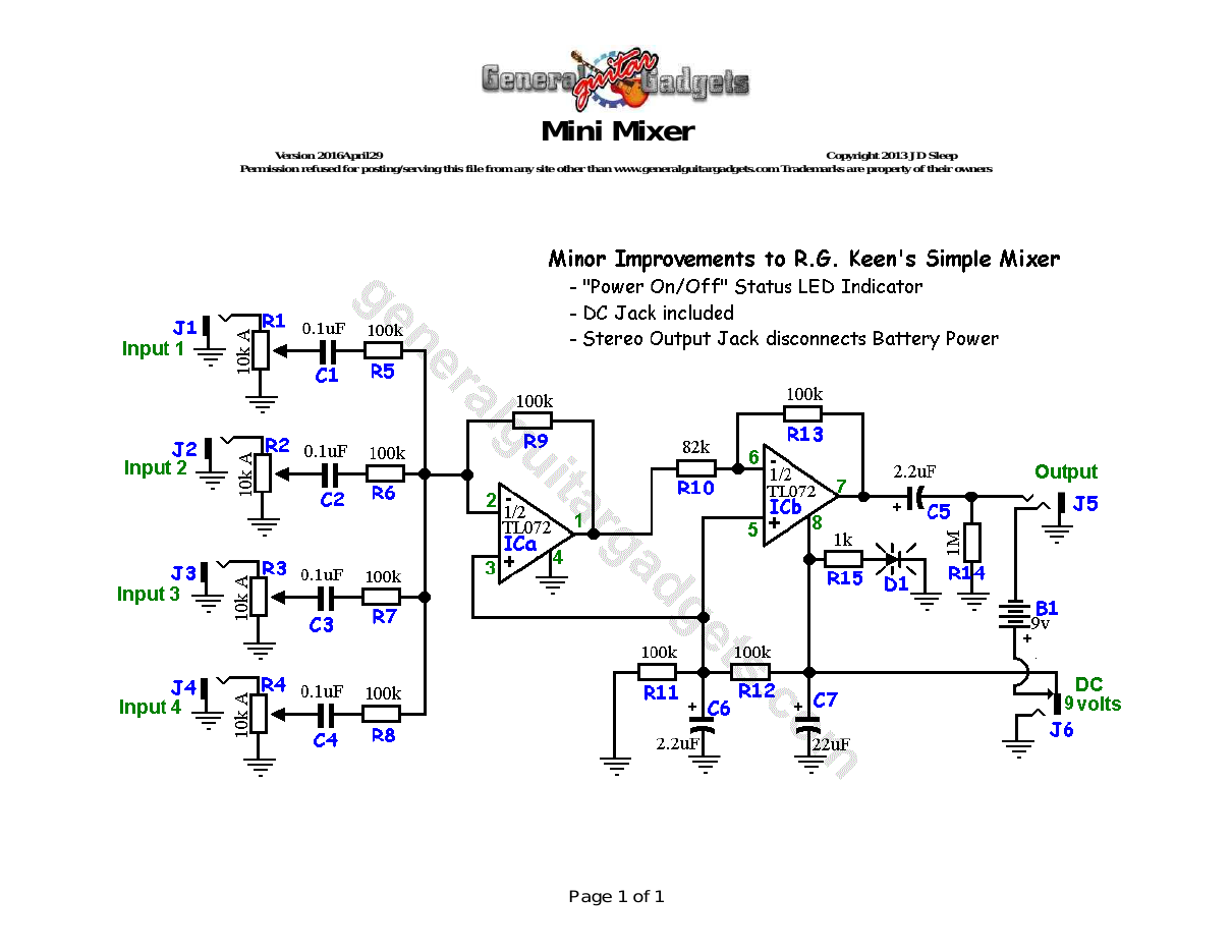
Parts layout
Parts Layout / Wiring Diagram
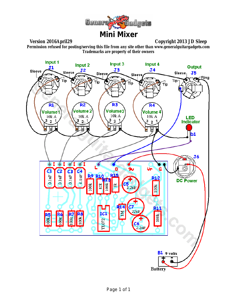
What you will need
Bill of Materials
Version 2016December08 · Copyright 2013, 2016 JD Sleep · Permission refused for posting/serving this file from any site other than www.generalguitargadgets.com · Trademarks are property of their owners
Resistors
| Resistor ID | Value | 3-band Marking | 4-band Marking |
|---|---|---|---|
| R1 | (10k A Potentiometer) | ||
| R2 | (10k A Potentiometer) | ||
| R3 | (10k A Potentiometer) | ||
| R4 | (10k A Potentiometer) | ||
| R5 | 100k | brown-black-yellow | brown-black-black-orange |
| R6 | 100k | brown-black-yellow | brown-black-black-orange |
| R7 | 100k | brown-black-yellow | brown-black-black-orange |
| R8 | 100k | brown-black-yellow | brown-black-black-orange |
| R9 | 100k | brown-black-yellow | brown-black-black-orange |
| R10 | 82k | grey-red-orange | Grey-red-black-red |
| R11 | 100k | brown-black-yellow | brown-black-black-orange |
| R12 | 100k | brown-black-yellow | brown-black-black-orange |
| R13 | 100k | brown-black-yellow | brown-black-black-orange |
| R14 | 1M | brown-black-green | brown-black-black-yellow |
| R15 | 1k | brown-black-red | brown-black-black-brown |
Capacitors
| Capacitor ID | Value | Type | Possible Marking |
|---|---|---|---|
| C1 | 0.1µF | Film or ceramic | 104 or 1k |
| C2 | 0.1µF | Film or ceramic | 104 or 1k |
| C3 | 0.1µF | Film or ceramic | 104 or 1k |
| C4 | 0.1µF | Film or ceramic | 104 or 1k |
| C5 | 2.2µF | Aluminum Electrolytic | 2.2µF |
| C6 | 2.2µF | Aluminum Electrolytic | 2.2µF |
| C7 | 22µF | Aluminum Electrolytic | 22µF |
Potentiometers
| Part ID | Value | Type |
|---|---|---|
| R1 - Volume Control Channel 1 | 10k | Audio (log) Taper |
| R2 - Volume Control Channel 2 | 10k | Audio (log) Taper |
| R3 - Volume Control Channel 3 | 10k | Audio (log) Taper |
| R4 - Volume Control Channel 4 | 10k | Audio (log) Taper |
Other
| Part ID | Part Name |
|---|---|
| D1 | LED |
| IC1 | TL072 or other dual opamp |
| J1 | Mono quarter-inch jack |
| J2 | Mono quarter-inch jack |
| J3 | Mono quarter-inch jack |
| J4 | Mono quarter-inch jack |
| J5 | Stereo quarter-inch jack |
| J6 | DC Jack |
| B1 | 9 volt battery (not included in the Kit) 9v battery snap, Printed Circuit Board, 24 gauge stranded wire, IC Socket Enclosure, Knobs |
How to build it
Instructions
Version 2016April29 · Copyright 2013 JD Sleep · Permission refused for posting/serving this file from any site other than www.generalguitargadgets.com · Trademarks are property of their owners
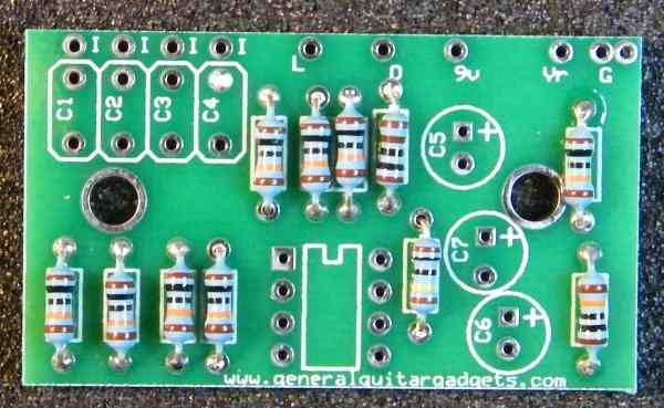
This is a Four Channel, Mono Output Mini Mixer. A great tool to have in your home studio or on your pedal board for parallel effect chains. This is a fairly simple kit to build. Follow the Bill of Materials, the Layout Diagram and General Build Instructions. 1 – Mount the potentiometers, knobs, LED and jacks onto the enclosure as shown above. 2 – Populate the resistors onto the PCB. Special note about resistor R10: R10 value controls how much gain the mixer will give. The lower the resistor value the higher the gain/volume you can get from the mixer. We have found that higher gains produce more white noise from the output. We settled on an 82k resistor for the kits since this give about unity gain and keeps the background noise down.
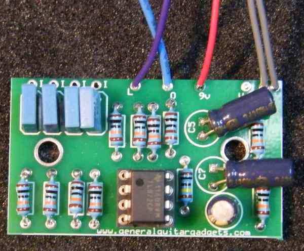
3 – Populate the capacitors and the IC socket onto the PCB. It's good to bend the tall electrolytic capacitors down flat as in the photo below so that the PCB has a low profile.
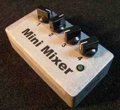
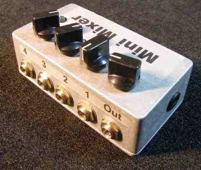
4 – Solder the wires into the pads on the PCB. Insert the IC into the socket.
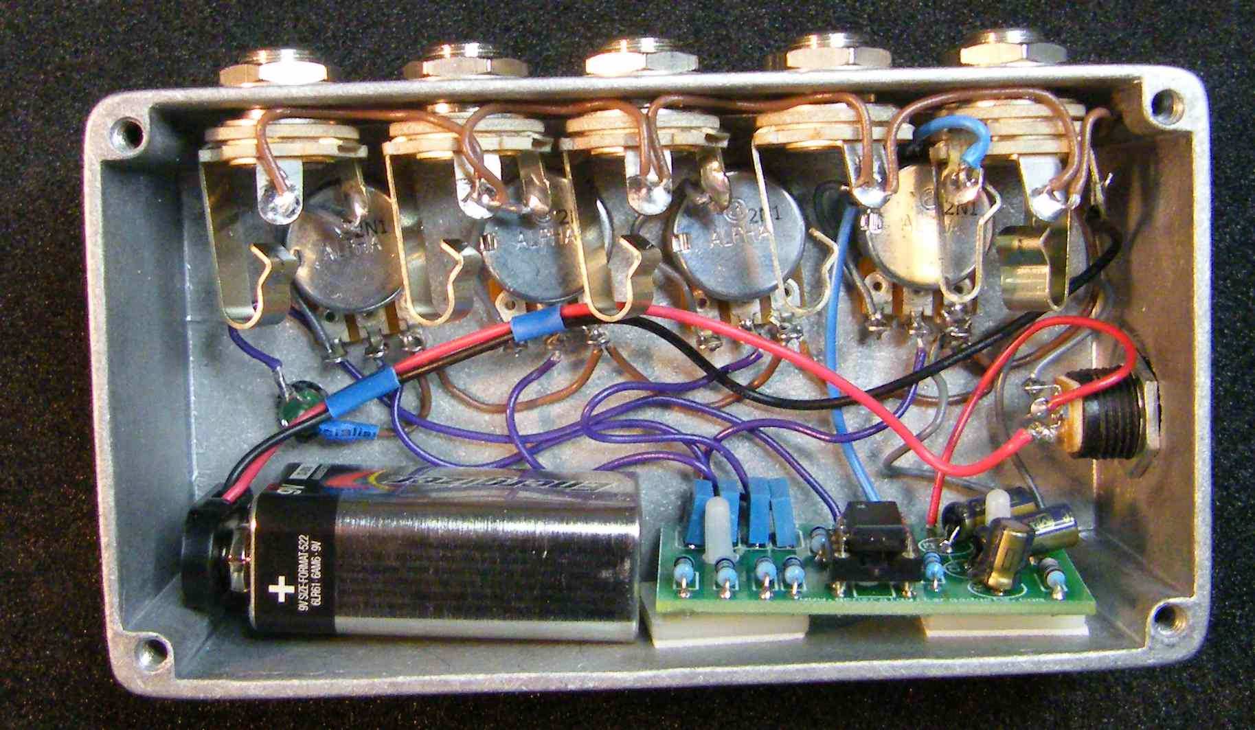
5 – Wire the circuit together as shown in wiring diagram (and the photo below). Here's an inside view of the unit we built to give you some general ideas if needed.
Here is a chart of voltages taken at the IC pins. Use these voltages as a guideline. You may not get the exact readings listed, but should be somewhere in the area.
Component
Location
9 volt power supply
Voltage
9v
IC1
Pin 1
4.5v
IC1
Pin 2
4.5v
IC1
Pin 3
4.5v
IC1
Pin 4
0v
IC1
Pin 5
4.5v
IC1
Pin 6
4.5v
IC1
Pin 7
4.5v
IC1
Pin 8
9v
Comments and questions are welcome and can be sent to [email protected]
More about this project
Notes, sounds and related links


Ready to build? We have the kit.
Buy a Mini Mixer Complete Kit. Includes all the parts and materials you need to build one, all for about the price you would pay for a PCB and parts.
Would you like a Ready to Solder Circuit Board for this project?