
Project · Bass
BRASSM - Maestro™ Brass Master™ Replica
This is a Maestro™ Brass Master™ replica project. This project is courtesy of GEOFEX (note: this external site does not use a secure HTTPS connection).
The story
About the circuit
Maestro™, Gibson's effects brand, released the Brass Master™ in the early 1970s as a fuzz for bass players. It generates an octave-up fuzz and lets you blend it with the clean signal, with a switch for two different harmonic voicings, so the bottom end stays intact while the fuzz sits on top: the "brass" in the name is the brassy, horn-like upper harmonics it adds. Originals are rare, and the circuit was documented for the DIY world by R.G. Keen at GEOFEX.
This project at GGG
Our Brass Master™ replica comes from that GEOFEX documentation, with thanks to R.G., laid out for a standard stompbox enclosure. It has been one of the quiet steady sellers on the site, mainly to bass players who have run out of fuzzes that don't lose the low end. The kit includes everything you need; the schematic and layout are below.
Project files
Everything you need to build it
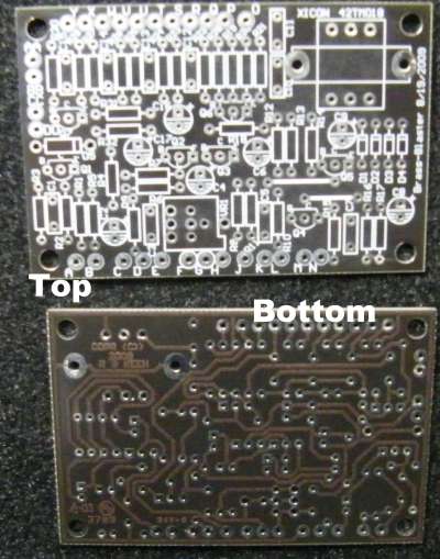
Brass Master™ Ready-For-Transfer Printed Circuit Board Layout For use only if you are a complete DIY person who wants to etch and drill your own PCB. Otherwise, we recommend you ignore this PCB mask and buy the Ready to Solder Printed Circuit Board or Complete Kit.
Schematic
Schematic
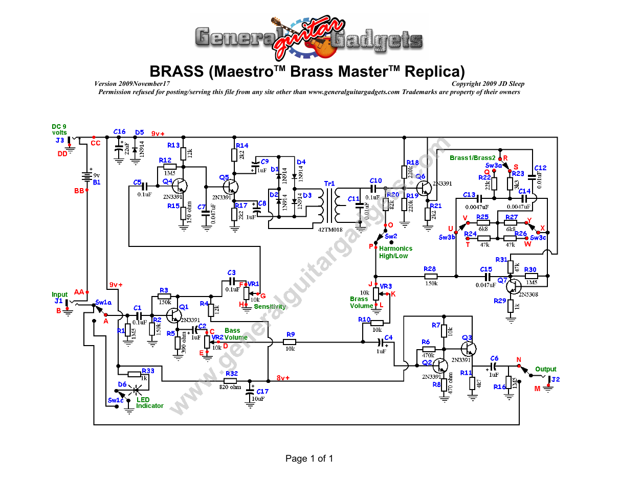
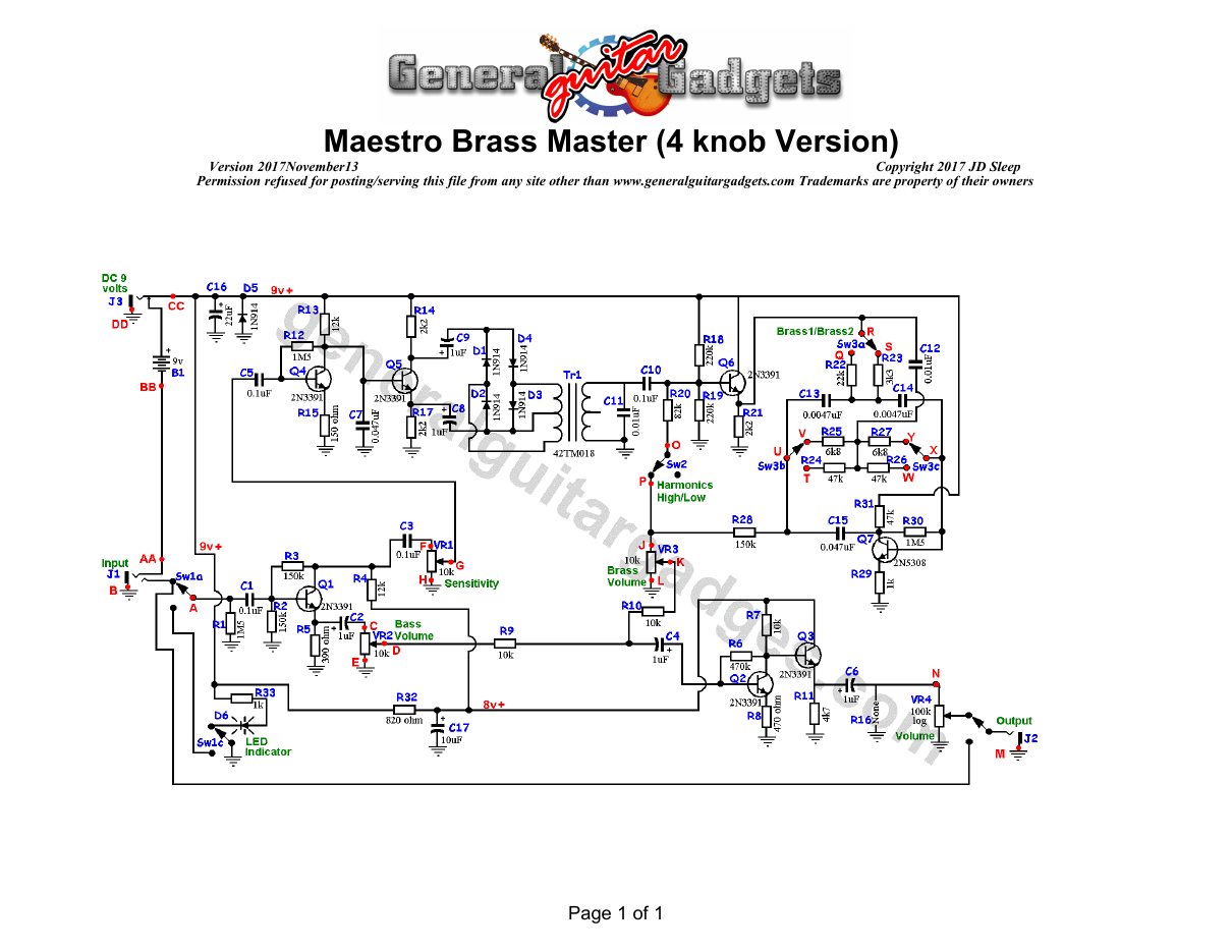
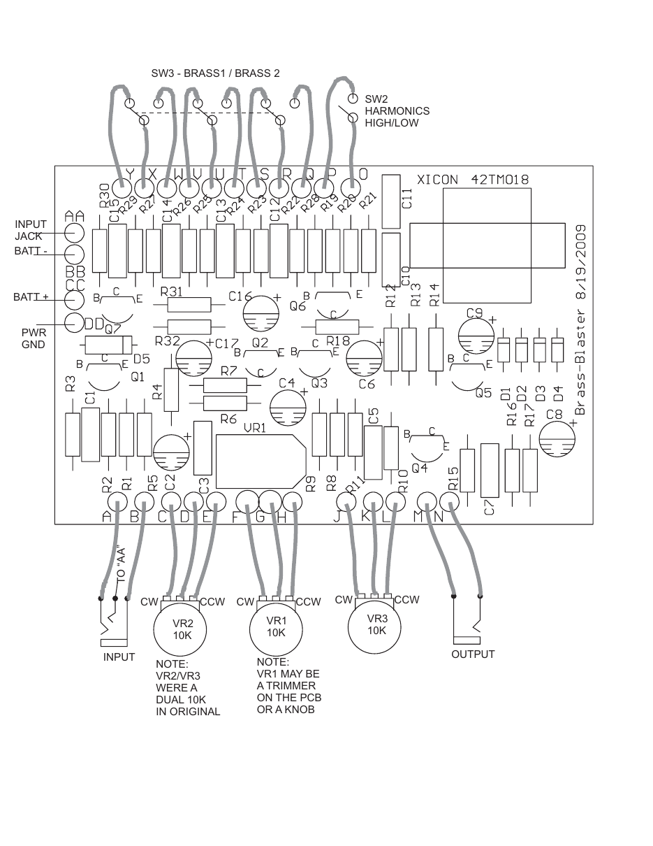
Parts layout
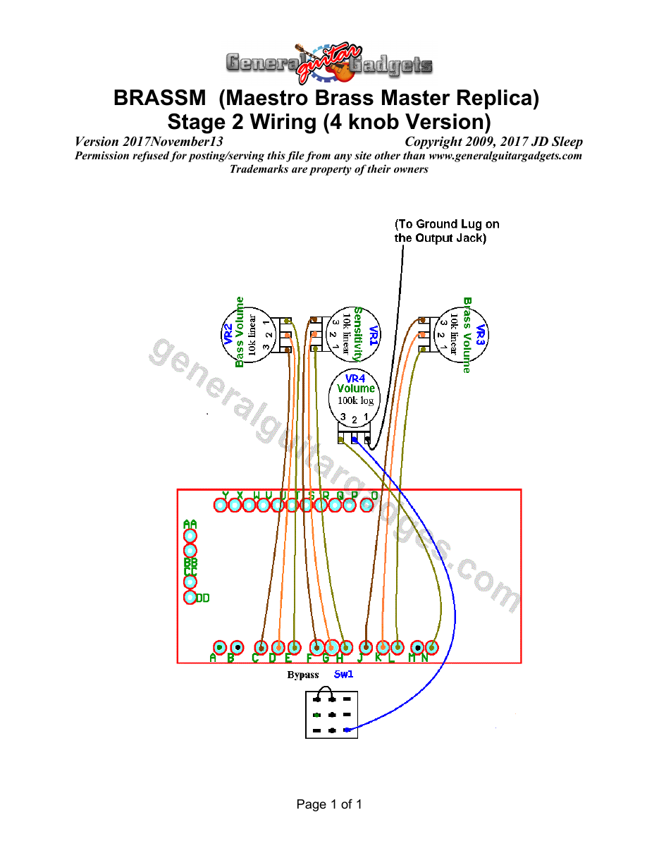
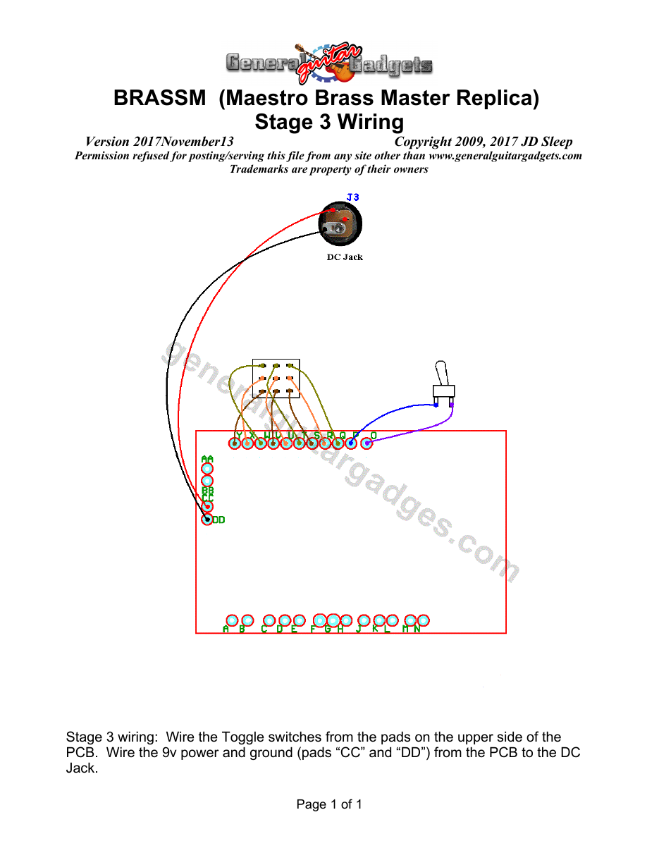
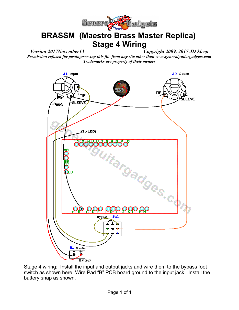
Parts Layout / Wiring Diagram
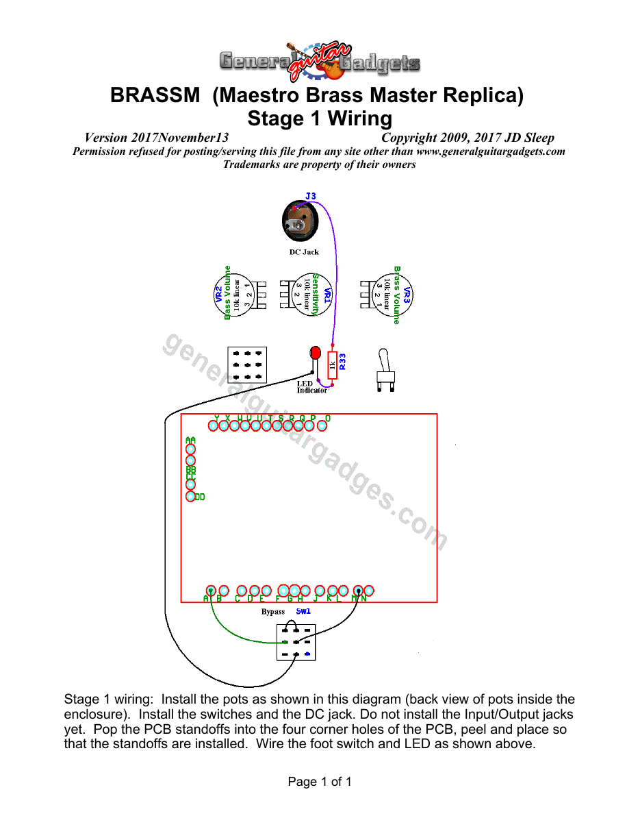
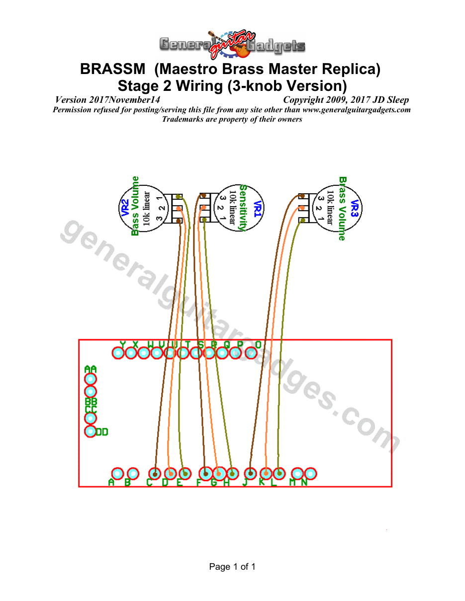
What you will need
Bill of Materials
Version 2017November13 · Copyright 2009, 2017 JD Sleep · Permission refused for posting/serving this file from any site other than www.generalguitargadgets.com · Trademarks are property of their owners
Resistors
| Resistor ID | Value | 3-band Marking | 4-band Marking |
|---|---|---|---|
| R1 | 1M5 (1.5M) | brown-green-green | brown-green-black-yellow |
| R2 | 150k | brown-green-yellow | brown-green-black-orange |
| R3 | 150k | brown-green-yellow | brown-green-black-orange |
| R4 | 12k | brown-red-orange | brown-red-black-red |
| R5 | 390 ohm | orange-white-brown | orange-white-black-black |
| R6 | 470k | yellow-violet-yellow | yellow-violet-black-orange |
| R7 | 10k | brown-black-orange | brown-black-black-red |
| R8 | 470 ohm | yellow-violet-brown | yellow-violet-black-black |
| R9 | 10k | brown-black-orange | brown-black-black-red |
| R10 | 10k | brown-black-orange | brown-black-black-red |
| R11 | 4k7 (4.7k) | yellow-violet-red | yellow-violet-black-brown |
| R12 | 1M5 (1.5M) | brown-green-green | brown-green-black-yellow |
| R13 | 12k | brown-red-orange | brown-red-black-red |
| R14 | 2k2 (2.2k) | red-red-red | red-red-black-brown |
| R15 | 150 ohm | brown-green-brown | brown-green-black-black |
| R16 | 1M5 (1.5M) (Not needed if you have Volume Pot) | brown-green-green | brown-green-black-yellow |
| R17 | 2k2 (2.2k) | red-red-red | red-red-black-brown |
| R18 | 220k | red-red-yellow | red-red-black-orange |
| R19 | 220k | red-red-yellow | red-red-black-orange |
| R20 | 82k | gray-red-orange | gray-red-black-red |
| R21 | 2k2 (2.2k) | red-red-red | red-red-black-brown |
| R22 | 22k | red-red-orange | red-red-black-red |
| R23 | 3k3 (3.3k) | orange-orange-red | orange-orange-black-brown |
| R24 | 47k | yellow-violet-orange | yellow-violet-black-red |
| R25 | 6k8 (6.8k) | blue-gray-red | blue-gray-black-brown |
| R26 | 47k | yellow-violet-orange | yellow-violet-black-red |
| R27 | 6k8 (6.8k) | blue-gray-red | blue-gray-black-brown |
| R28 | 150k | brown-green-yellow | brown-green-black-orange |
| R29 | 1k | brown-black-red | brown-black-black-brown |
| R30 | 1M5 (1.5M) | brown-green-green | brown-green-black-yellow |
| R31 | 47k | yellow-violet-orange | yellow-violet-black-red |
| R32 | 820 ohm | gray-red-brown | gray-red-black-black |
| R33 | 1k | brown-black-red | brown-black-black-brown |
Capacitors
| Capacitor ID | Value | Type | Possible Marking |
|---|---|---|---|
| C1 | 0.1µF | Film | 104 |
| C2 | 1µF | Aluminum Electrolytic | 1µF |
| C3 | 0.1µF | Film | 104 |
| C4 | 1µF | Aluminum Electrolytic | 1µF |
| C5 | 0.1µF | Film | 104 |
| C6 | 1µF | Aluminum Electrolytic | 1µF |
| C7 | 0.05µF (or 0.047µF) | Film | 503 (or 473) |
| C8 | 1µF | Aluminum Electrolytic | 1µF |
| C9 | 1µF | Aluminum Electrolytic | 1µF |
| C10 | 0.1µF | Film | 104 |
| C11 | 0.01µF | Film | 103 |
| C12 | 0.01µF | Film | 103 |
| C13 | 0.005µF (or 0.0047µF) | Film | 502 ( or 472 or 4n7) |
| C14 | 0.005µF (or 0.0047µF) | Film | 502 ( or 472 or 4n7) |
| C15 | 0.05µF (or 0.047µF) | Film | 503 (or 473) |
| C16 | 25µF (or 22µF) | Aluminum Electrolytic | 25µF |
| C17 Potentiometers | 10µF Part Id | Aluminum Electrolytic | 10µF Value |
| VR1 (Sensitivity) | 10k linear | ||
| VR2 (Bass Volume Control) | 10k linear | ||
| VR3 (Brass Volume Control) | 10k linear | ||
| VR4 (Volume Control | 100k Log |
Other
| Part ID | Part Name |
|---|---|
| D1 | 1N914 or 1N4001 |
| D2 | 1N914 or 1N4001 |
| D3 | 1N914 or 1N4001 |
| D4 | 1N914 or 1N4001 |
| D5 (Optional, Not included in the Kit) | 1N4003 |
| Q1 | 2N3391 (or 2N3392) |
| Q2 | 2N3391 (or 2N3392) |
| Q3 | 2N3391 (or 2N3392) |
| Q4 | 2N3391 (or 2N3392) |
| Q5 | 2N3391 (or 2N3392) |
| Q6 | 2N3391 (or 2N3392) |
| Q7 | 2N5308 |
| T1 | 42TM018 Transformer (mouser.com part #) |
| J1 | Stereo quarter-inch jack |
| J2 | Mono quarter-inch jack |
| J3 | DC Jack |
| B1 | 9 volt battery |
| Sw1 | Heavy Duty 3PDT footswitch (bypass) |
| Sw2 (Brass 1 & 2) | 3PST or 3PDT |
| Sw3 (Harmonic Hi/Low) | SPST toggle switch 9v battery snap & holder, Copper-clad board & etchant, or perfboard 24 gauge stranded wire, knobs Enclosure |
Notes
VR2 and VR3 can be a dual-gang 10k pot each wired opposite so that it functions as a mix control.
How to build it
Instructions
Version 2017November13 · Copyright 2009, 2017 JD Sleep · Permission refused for posting/serving this file from any site other than www.generalguitargadgets.com · Trademarks are property of their owners
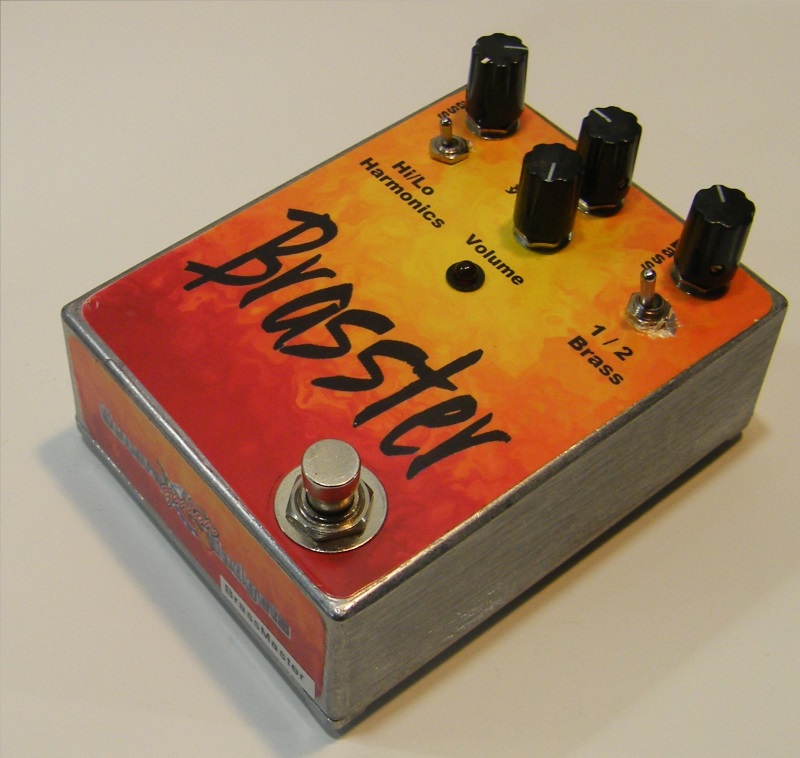
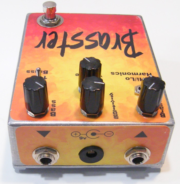
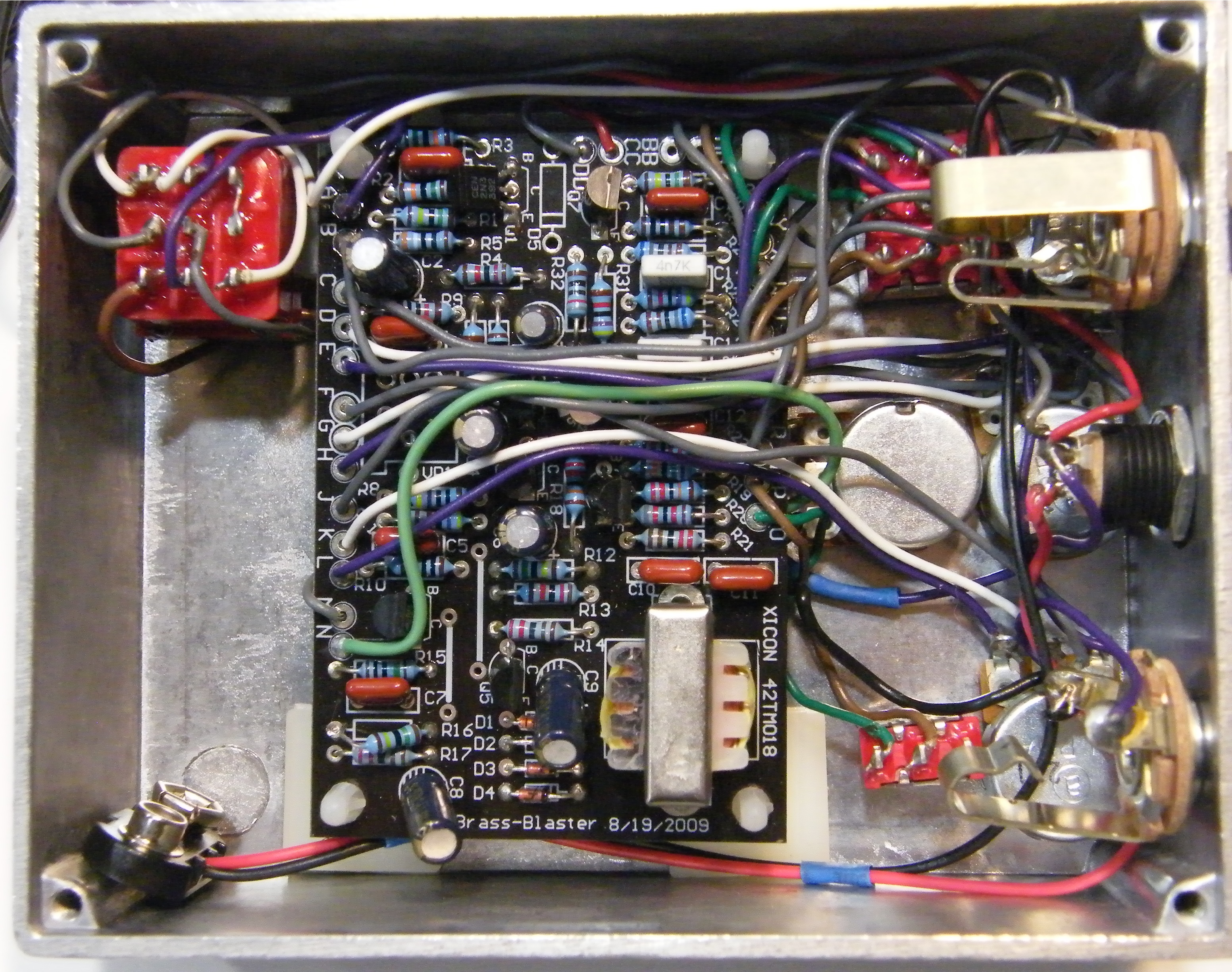
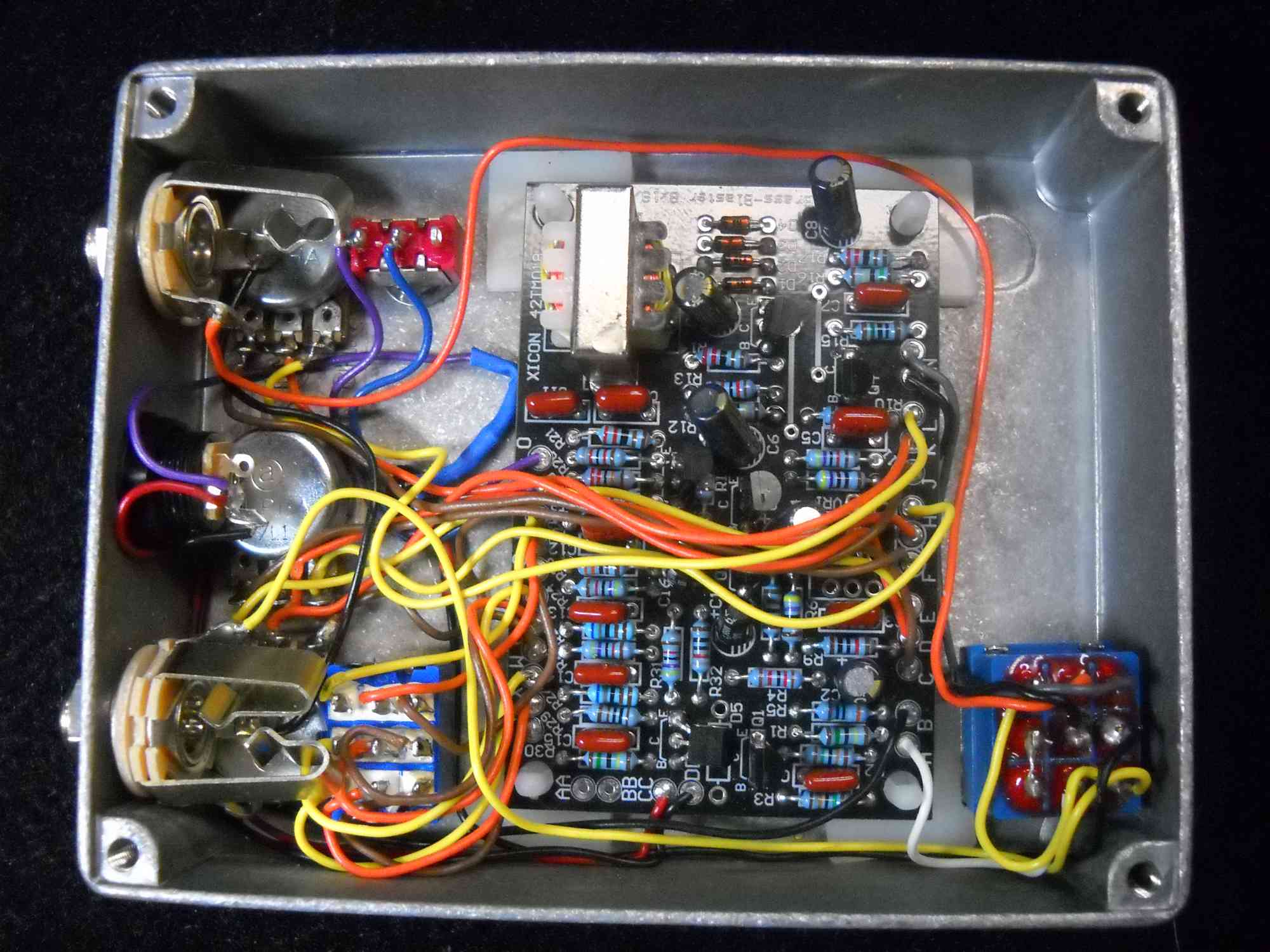
This is a replica of the Maestro™ Brass Master™ referred to in these documents as BRASSM. Do not attempt to build this project unless you have some experience building effects. There are a lot of parts and there is a lot of off-board wiring involved. We have divided the wiring instructions into four stages and also a separate diagram for parts placement on the PCB. Each diagram contains only what is being installed in the given stage. There is no diagram that shows all the wires connected since there are so many wires the diagram would be difficult to follow. The original version had 3 knobs, Brass, Bass and Sensitivity controls. We found that an added Volume control is useful, since some of the settings can raise the volume level considerably and that is not always a good thing when you switch the effect in/out. In some of the photos, we did not installed a battery snap, just the DC jack. We did not use pads “AA” and “BB” and we wired the battery snap wires directly to the input jack as the Stage 4 wiring diagram shows. It should be noted that with this much wiring and having off-board wiring pads on three sides of the PCB, you can easily wire it in to the enclosure so that you can’t get access to the bottom of the PCB. It is a good idea to wire it so that can examine or re-solder the bottom of the PCB if needed. If you route all the wiring up and over toward the edge of the board with pads “O” through “Y”, you will still be able to lift the board up from the “switch side” of the PCB. Hopefully you can see that we wired ours this way in the gut-shot photos shown below.
Building Steps
1. Populate the PCB. Follow the Parts Placement Diagram. You do not need to install the two jumpers (indicated by thick red lines on the Parts Placement Diagram) These jumpers are built into the top layer of the PCB. The transformer can be installed with the primary facing either way, it doesn't matter. Watch the polarity of the aluminum electrolytic capacitors. Note that we did not install D5 protection diode (1N4003) it is not needed for operation and is not included in the kit. When you use the Volume Control, R16 is not needed, so don’t populate R16 if you are building the 4 knob version. If you look closely at the photo below, the R16 is lifted to disable it. 2. Stage 1 Wiring. Hook up the LED indicator as shown in this diagram. There is no spot on the PCB for the “current limiting resistor” for the LED, so it will have to be solder-tacked to the LED and wire. Note that if you build the 4-knob version, the LED will need to go under the PCB. The standoffs provided in the kit are extra tall so that it will easily fit under the PCB. Also wire the PCB input and Pad “M” (ground) to the bypass switch. It is not shown in the diagram for simplicity’s sake, but route these wires (from pads A and M) over the front side of the PCB and back under so that you can have easy access to the bottom of the board (for service purposes) if needed. 3. Stage 2 Wiring. Wire the potentiometers. Use “2A” diagram if you build the 3knob or the “2B” diagram if you build the 4-knob. The volume knob lug 2 wire should route under the PCB, again, for access to the bottom of the PCB. 4. Stage 3 Wiring. Wire the toggle switches and wire the power wires to the DC Jack as shown in this diagram. 5. Stage 4 Wiring. Wire the input and output signal and ground wires to the jacks. Hook up the battery snap to the DC jack and the input sleeve lug.
Here's an inside view of the unit we built to how it looks when assembled in a 1590BB tall enclosure. It is a very tight fit. The potentiometers should to be turned sideways from how we normally install them. Have fun, comments and questions are welcome and can be sent to [email protected]
4 Knob
3 Knob
More about this project
Notes, sounds and related links

Ready to build? We have the kit.
Buy a Maestro™ Brass Master™ replica Complete Kit. Includes all the parts and materials you need to build one, all for about the price you would pay for a PCB and parts.
Would you like a Ready to Solder Circuit Board for this project? Note: If you buy the kit, the Ready-to-Solder Circuit Board (RTS PCB) is included in the kit. You do not need to purchase this RTS PCB if you buy the kit.