
Four Output Isolated
A power supply project with 4 isolated outputs from Scott Swartz. There are options to choose what voltages the outputs are to be. This board works for 115V and 230V AC inputs, based on the transformer selection.
I have shortened the name to SS-PS4 in some cases.
- SS-PS4 Power Supply Bill of Materials text file
- SS-PS4 Power Supply Bill Parts Layout and Wiring Diagram
- SS-PS4 Power Supply PDF Schematic file
- SS-PS4Power Supply PDF Ready-For-Transfer Printed Circuit Board Layout PDF File
Four Output Isolated Power Supply
By Scott Swartz
Copyright 2002, All Rights Reserved
First, some notes about electrical safety.
- This project uses wall AC power, the DANGEROUS stuff. Please follow the recommendations below when building this project.
- Use a 3 prong AC cord and make sure the green wire safety ground is connected solidly to the enclosure.
- Keep in mind there is 120 VAC on some of the traces! Mount the PC board on round or hex standoffs at least a ¼ inch high by at least ¼ inch diameter with 6-32 threads. DO NOT use adhesive back plastic standoffs, they are not reliable or strong enough for a board with two transformers on it!
- You must use a strain relief for the AC cord. This prevents the cord from getting cut on the sharp edges of the metal enclosure and also prevents the cord from getting ripped off the PC board.
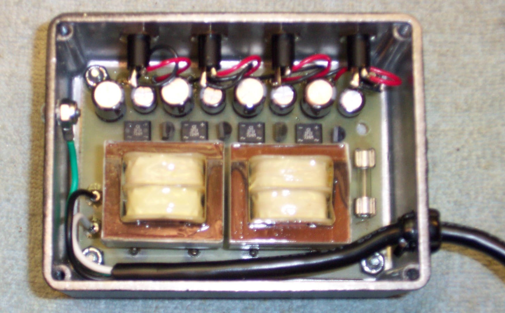
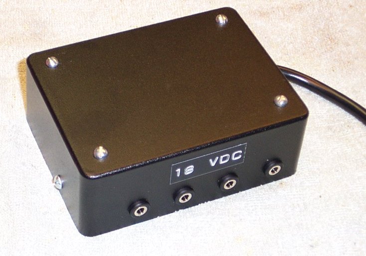
I built the prototype in a Hammond 1590S box, which is 3.2 x 4.3 x 1.6 inches. As you can see from the pics, it is tight, but can be done. For a little easier wiring and a more common box size, the Hammond 1590C would work well, 3.7 x 4.7 x 2.2, its the same size as the 1590BB but taller.
I like to use eyelets for pads that get wires, in this case the AC power connection and the 4 pairs of DC power connections. An advantage to this is that you can solder the wires from the component side of the PCB, if you make sure the eyelet and solder pad are well tinned prior to trying to solder from the component side. If you don?t use eyelets, I would recommend using a terminal strip for the AC cord so that you are not trying to get the strain relief installed with the PC board hanging off the end.
Be sure to use isolated jacks for the DC outputs, this is for two reasons. First, you want to be able to be able to connect the third prong safety ground of the 3 prong AC cord to the enclosure and not have it create a ground loop. Second and more obvious, for the 4 outputs to isolated, the DC grounds can’t be connected via the enclosure.
Electrical Design
Electrically, this is a very simple circuit times four. Transformer, to bridge rectifier/cap, to regulator with filter cap on regulated output, to the jacks.
The transformer should be selected to provide some margin for voltage drop across the regulator. The PCB layout assumes use of readily available Split Pack PCB mount transformers, which are available in a wide range of voltages. The following table summarizes my recommendations. Note that each transformer provides 2 voltage sources, since the 2 secondary windings are isolated and can be used independently. The Mouser catalog page does not state this (it shows series and parallel connections), but it works fine.
| Regulated Output Voltage | Input Voltage | Transformer Secondary Rating | Transformer Part Number, Mouser Electronics | Regulator Part Number, Mouser Electronics |
| 9 VDC | 115 VAC | 12 VAC at 45 ma | 553-F24-045 | 513-NJM78L09A |
| 12 VDC | 115 VAC | 18 VAC at 65 ma | 553-F36-65 | 513-NJM78L12A |
| 18 VDC | 115 VAC | 18 VAC at 65 ma | 553-F36-65 | 513-NJM78L18A |
| 9 VDC | 230 VAC | 12 VAC at 45 ma | 553-FS24-045 | 513-NJM78L09A |
| 12 VDC | 230 VAC | 18 VAC at 65 ma | 553-FS36-65 | 513-NJM78L12A |
| 18 VDC | 230 VAC | 18 VAC at 65 ma | 553-FS36-65 | 513-NJM78L18A |
The transformers shown above for 115 VAC applications have only 2 pins for the primary winding and do not connect to some of the pads on the PCB layout.The transformers shown for 230 VAC applications (Europe, etc) have 4 pins that connect to all the pads shown on the PCB layout and automatically give the correct winding ratio.
Note that by selecting the appropriate transformers and regulators, one PCB can be built to provide 2 pairs of 2 different output voltages.
The schematic shows a 1/8 amp fuse, which is plenty of allowance for inrush current. DO NOT use a higher amperage fuse than this. The theoretical current draw for the two 2.5 VA transformers is only 42 milliamps at 120 VAC, so a 1/16 amp fuse will probably work also.
Four Output Isolated Power Supply Pictures
copyright 2002 by Scott Swartz. All rights reserved.
Here’s some pictures of Scott’s Four Output Isolated Power Supply in a Hammond enclosure: